
Electric Longboard
While a friend and I were walking around campus, we were passed by someone riding an electric longboard which immediately sparked a conversation about how expensive they are and how we could definitely build a faster board for a fraction of the cost. I treated this as more or less of a personal challenge to try to build my own electric longboard with competitive specs and at a competitive price point. After a few months of research, I learned about the anatomy of an electric longboard and what I would need to do to make everything come together. The whole project took me about 6 months and at the end I was able to achieve speeds of ~27mph with a range of more than 10 miles. While I was able to make a great board it was definitely not as robust as many of the pre-made boards, and there was plenty of room for improvement.
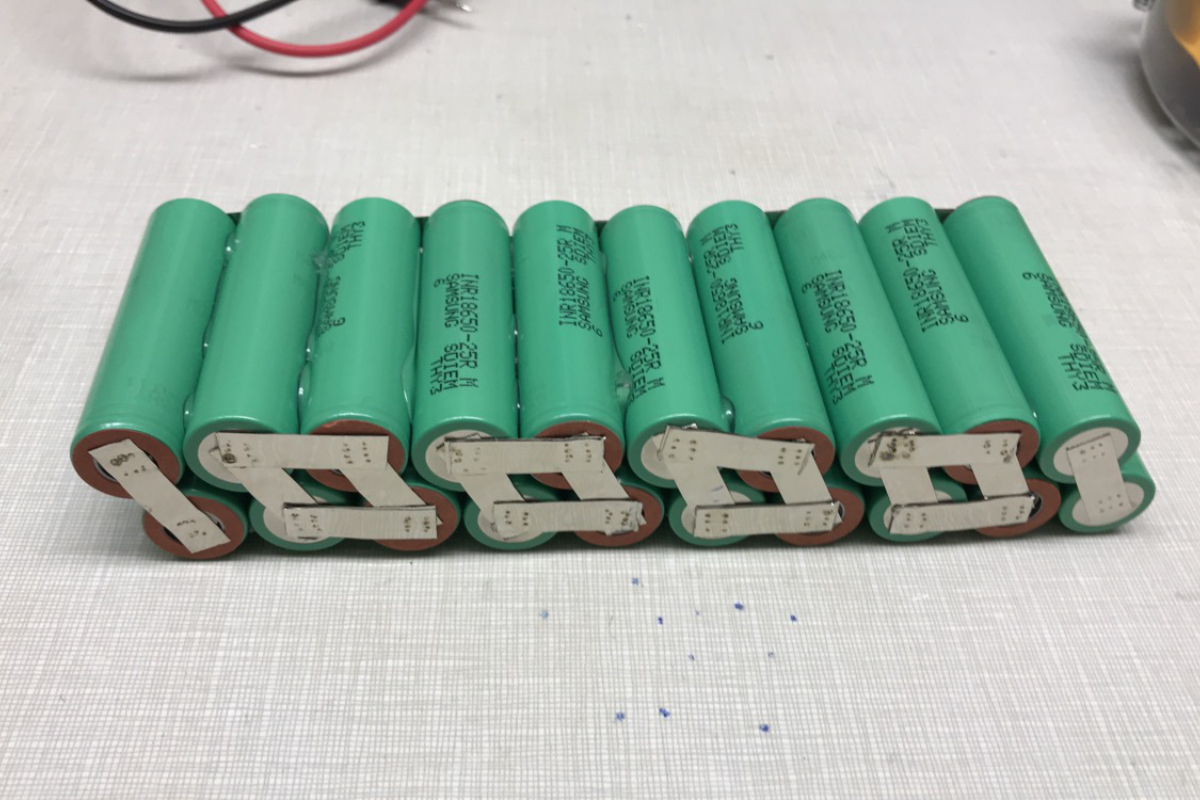
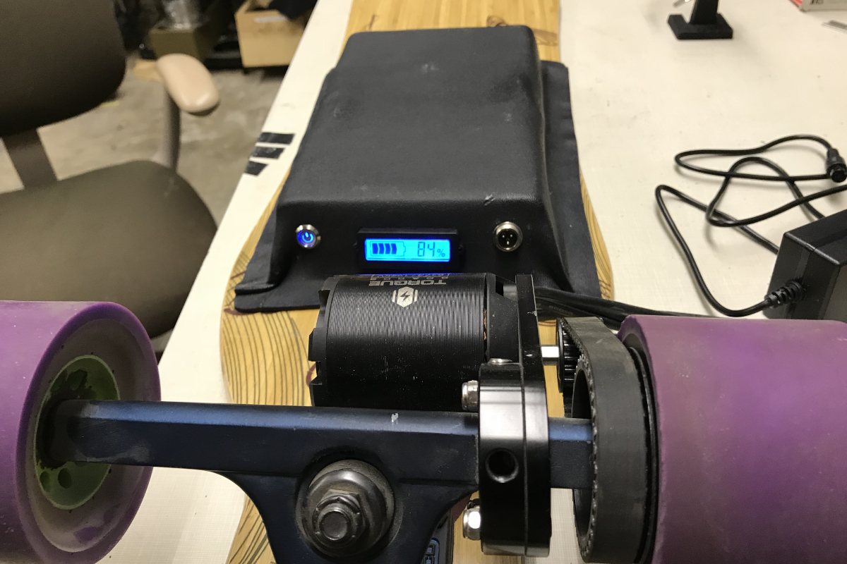
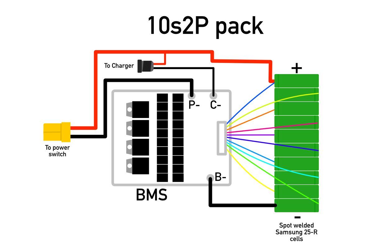
When designing the board, I was adamant about building my own battery pack because buying one seemed like cheating (and the pre-made ones are just so damn expensive). I decided to make a 10s2p pack from 18650 cells to supply enough voltage to achieve a reasonable top speed and have a pretty decent range while keeping to a relatively small form factor. I made my pack using the Samsung 25-R because at the time it was one of the batteries with the highest rated discharge current and capacity. Back then, I wasn’t aware of the voltage sag that those cells are known for and at some point I would like to upgrade to a new pack using the Samsung 30Q. To assemble my pack, I learned how to spot weld and welded the cells together with nickel strip. This process can be pretty dangerous if done improperly so I made sure to take a lot of time researching the process to make sure I made it as safe as possible. Once the cells were connected, I added a 10s BMS to the pack for balance charging and soldered all the leads to the my welded strips. I then wrapped everything in kapton tape, soldered on bullet connectors for charging, added an XT90 connector and wrapped the whole pack in heat shrink. I also wired up leads for a state of charge indicator which I mounted into the enclosure.
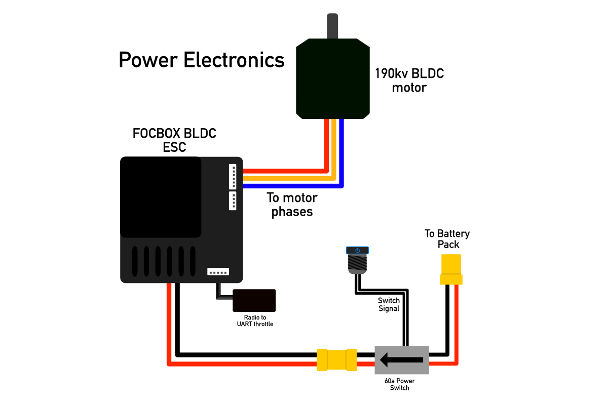
For the power electronics, I used a 190kv BLDC motor which was controlled using a FOCBOX ESC based on Benjamin Vedder’s VESC controller. I initially wanted to design my own BLDC controller but quickly realized that would greatly expand the scope of project and decided to spend my time tuning the parameter on the FOCBOX instead. The throttle is set up using a RF receiver which forwards a PPM signal generated by the handle held controller to the ESC. The drivetrain of the board is setup with an HTD5 belt and two pulleys. One mounts to the end of the motor shaft while the other is connected directly to the driven wheel.
I used a Loaded Vanguard for this build because I really wanted a flexible deck, something that many of the commercially available boards don’t have. I designed and molded my own enclosure using KYDEX thermoplastic. I first made a positive of the mold and a jig to press it out of wood, then I heated up the sheet of plastic. After that, I pressed the sheet into the mold using the jig and let it cool. After the sheet had cooled, I cut out holes to mount my indicator, power switch and charge port and cleaned up the edges with the angle grinder. To mount this enclosure to the deck, I drilled holes and added #6-32 threaded inserts into the deck and screwed in the enclosure.
Overall this project came together very well and it taught me a ton about working with electric vehicles, battery technology and the capabilities of BLDC motors. Prior to this project, I had only every worked with lead-acid batteries and brushed DC motors and this really helped me to understand the costs and benefits of these other technologies. I now ride my board to school basically every day that the weather allows (which in Rochester, NY is not nearly as often as I’d like).