
F4 Flight Controller
This project is actually just the first step in a larger vision I had inspired by the announcement of the Raspberry Pi CM4 back in the fall of 2020. This new compute module provides users with all the power of a modern single board computer in a tiny 55mm x 40mm package. The first thing that came to mind is the CM4 would make a fantastic companion computer for a low SWaP autonomous micro quad (hopefully sub-250g!). For example, you could design a carrier board for the CM4 that was also a flight controller running something like Ardupilot, PX4 or even INAV. This carrier board FC would handle the low level flight controls while the companion computer is responsible for the high level autonomy and planning.
While this was a pretty decent idea, I quickly realized it this would be extremely complicated for someone who had never really designed a flight controller before and no formal background in board design. I started by redefine the scope of the project to initially only include designing a normal 30mm x 30mm flight controller that would run some lighter-weight firmware like Betaflight or INAV and then progressing to an Ardupilot compatible board with more peripherals and the socket for the CM4.
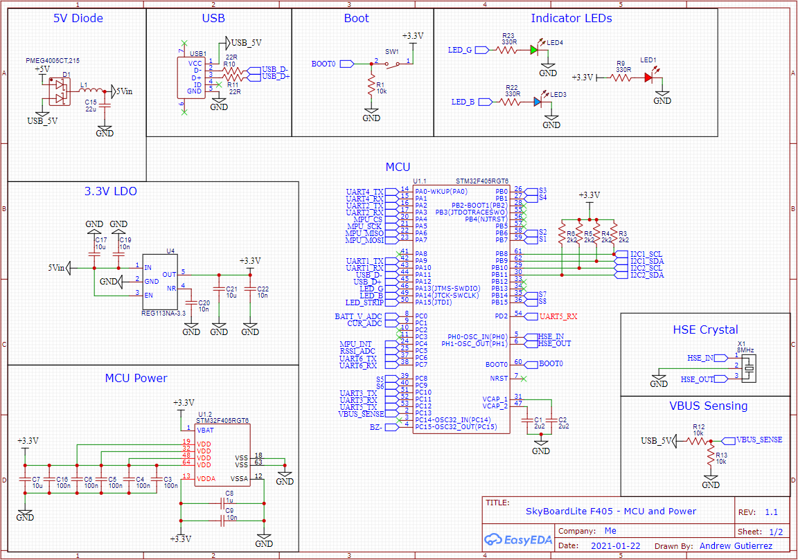
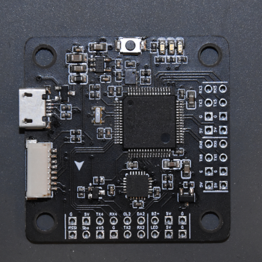
I chose to design the board around the STM32F405 because it strikes a good balance between price, performance and good IO. In addition, it’s a very popular FC chip so I would not have to redo the hardware definition files for the firmware. I also took inspiration from a number of open source hardware projects such as the OpenPilot Revolution as well as some commercial products like the Matek F405-SE board. These both influenced the initial list of features I wanted and helped me get a feel for the anatomy of a typical F4 flight controller. The first version of the board included all the essential components of a flight controller like 3.3V power regulation, USB connection for programming, an HSE Crystal and an MPU6000 IMU along with a couple bonus features such as a barometer, WS2812B LED socket and a hardware SBUS inverter for better RX compatibility. The board itself was designed in EasyEDA as a 4-layer board with a 3.3V plane, ground plane and two signal layers.
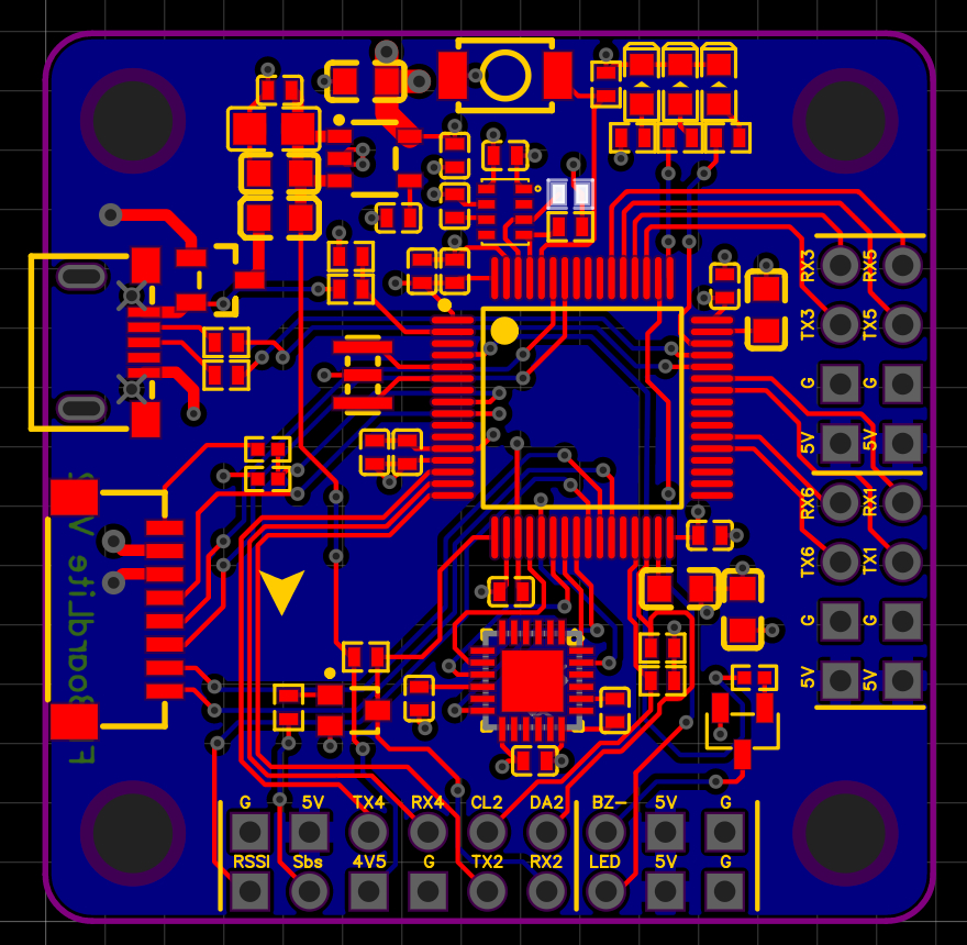
Once I finished designing and routing, I ordered the first run of boards and did some basic testing to make sure none of the power buses were shorted out and that all the important traces were properly connected. The next step was assembly. All the components are hand soldered surface mount parts because I really like making my life more difficult. In reality I had the option to get some of the components assembled with a pick-and-place machine but I decided to do them all myself for the sake of consistency plus it forced me to brush up on my soldering skills. I mostly used 0402 for the passive components unless there was a specific reason it needed to be larger, this helped saved space on the board since it started to get a little crowded by the end. Many of the components were mounted with solder paste and my hot air soldering station, however I really like drag soldering for QFN chips so I used a traditional soldering iron for the STM32.
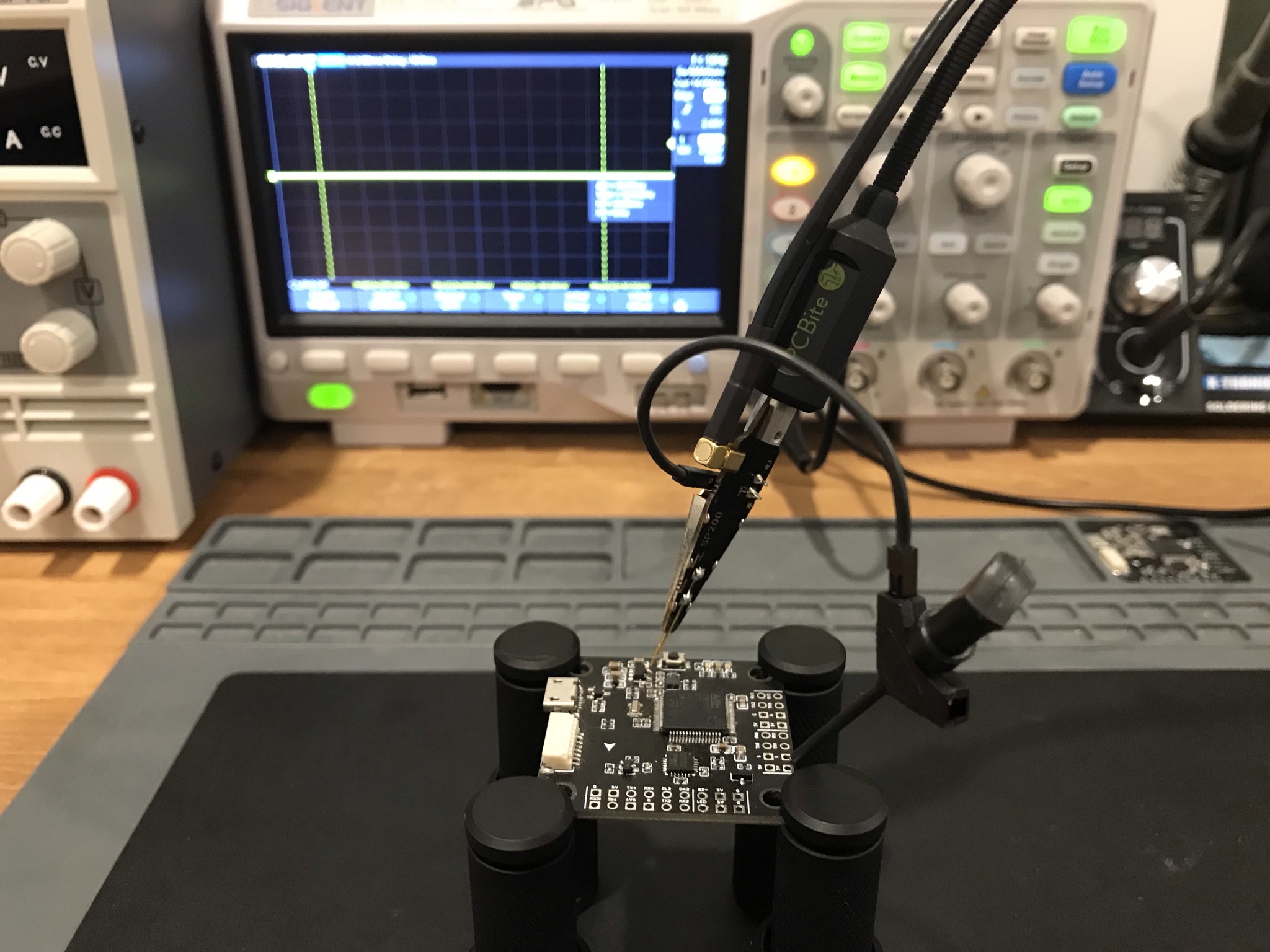
After the boards were assembled, I started the testing process to make sure all the power was being properly delivered and the MCU could properly communicate with the programming software over USB. I ran into a couple hardware bugs in the first couple iterations and quickly realized I would need to better test equipment to get a better idea of what was going on. At this point I got a little discouraged because I was able to successfully flash the MCU with INAV but it was not interfacing correctly with the companion software for some reason. I finally decided to invest in an oscilloscope which made my life much easier but just as things were starting to turn around, the 2021 global silicon shortage really started to pick up making it extremely difficult and costly to get more microcontrollers. Over the course of this project the STM32F405 I was using went from $6 a chip to over $28 each when if you could even find it in stock. At this point I decided to put the project on hold and focus on other things while the market stabilized but I fully intend to pick it back up when it makes sense. This is one of my favorite ideas I’e ever had and I’m really looking forward to seeing it to work for real.