
Lidar Scanning Robot
For my senior design project, our team of 4 mechanical engineers was tasked with designing a system that could non-invasively create a Digital Terrain Model (DTM) of a 100m x 100m area on a budget of $1000 in a semester. The DTM should only include the bare earth area, removing building and foliage from the model. This seemed like an extremely daunting task at the beginning given the scope of the project. While we were not quite able to meet all of those requirements, we were able to design and build a really cool system capable of creating point cloud models of an area of interest. The project almost entirely in C++ with the exception of one Python script used to remotely control the system from a laptop.
After considering a few different ways to collect the scan, we settled on using a plane lidar mounted on a robot that would travel across a rope mounted between two posts. By keeping track of the robot’s position across the rope and associating it with the plane data we are able to create a full 3D scan. The system was base on the Slamtec rpLidar A2M8 plane lidar because it has better range than some of the other rpLidar models and becuase it is one of the only lidar systems we could afford even though it still took nearly half of our budget. We used the SDK provided by Slamtec to interface with the sensor and then wrapped it with our own interface to make it easier for us to work with. To test the sensor, we made a custom UI using Qt and OpenGL to visualize the scans and ran simple 2D scans of different rooms and hallways.
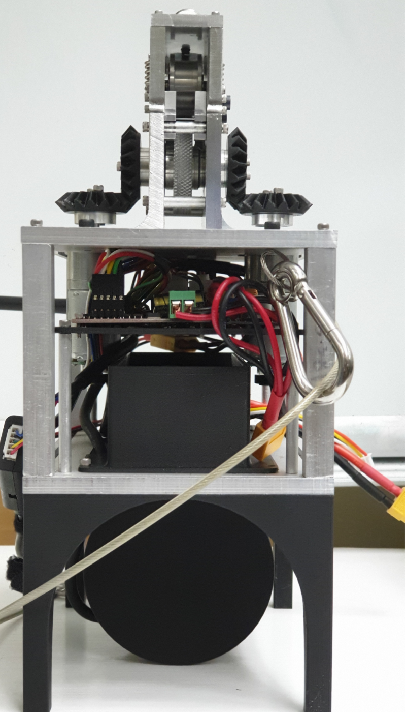
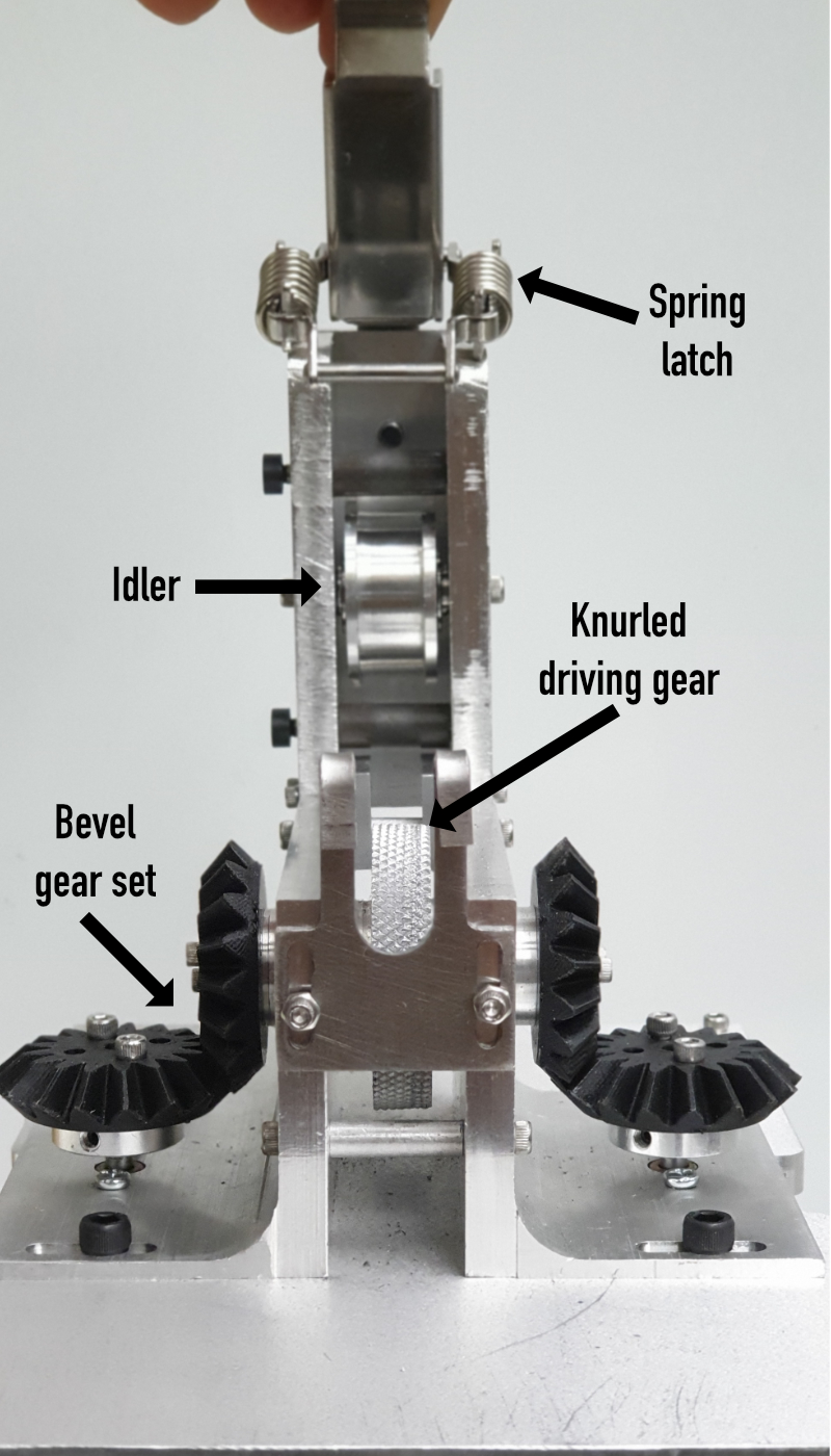
To get the robot to move across a rope, we used a set of two geared DC motors controlled with an H-bridge. These motors came packaged with rotary encoders which we used to determine how far the robot has traveled along the rope. The motors mount to a single drive shaft and compressed between a set of pulleys. We knurled the pulley on the driveshaft on the lathe to create friction against the rope and prevents the rope from slipping. In order to compress the two pulleys, we used a spring latch. In addition, the whole top half of the mechanism separates from the system allowing the user to clip the robot to a pre-strung rope without having to untie the cable and thread it through. To prevent off axis loading on the motors, we used a set of bevel gears to convert power from the motors to the driving pulley and a set of bearing along the shaft also help manage the loading. All of the mechanical parts of the robot were either 3D printed by the team or machined from aluminum either on the mill, lathe, laser cutter or CNC.
The robot is controlled over a USB radio telemetry module and receives high level commands from the control UI on a laptop, and the system sends some of the point-cloud data back over radio. Unfortunately, the radio does not have the high bandwidth needed to send the dense point cloud, so only some data is sent back while the full point cloud is logged to the robot. The computational core of the robot is a Raspberry Pi 3B+ which is set up to log the point-cloud data to the SD card. The system is power by a 3S2P 10,000mAh Li-Po battery pack which gets stepped down to 5V for the logic circuitry and used directly to power the motors.
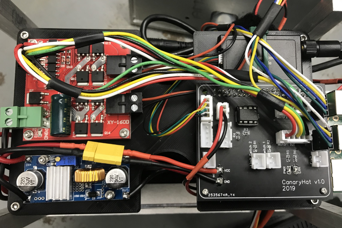
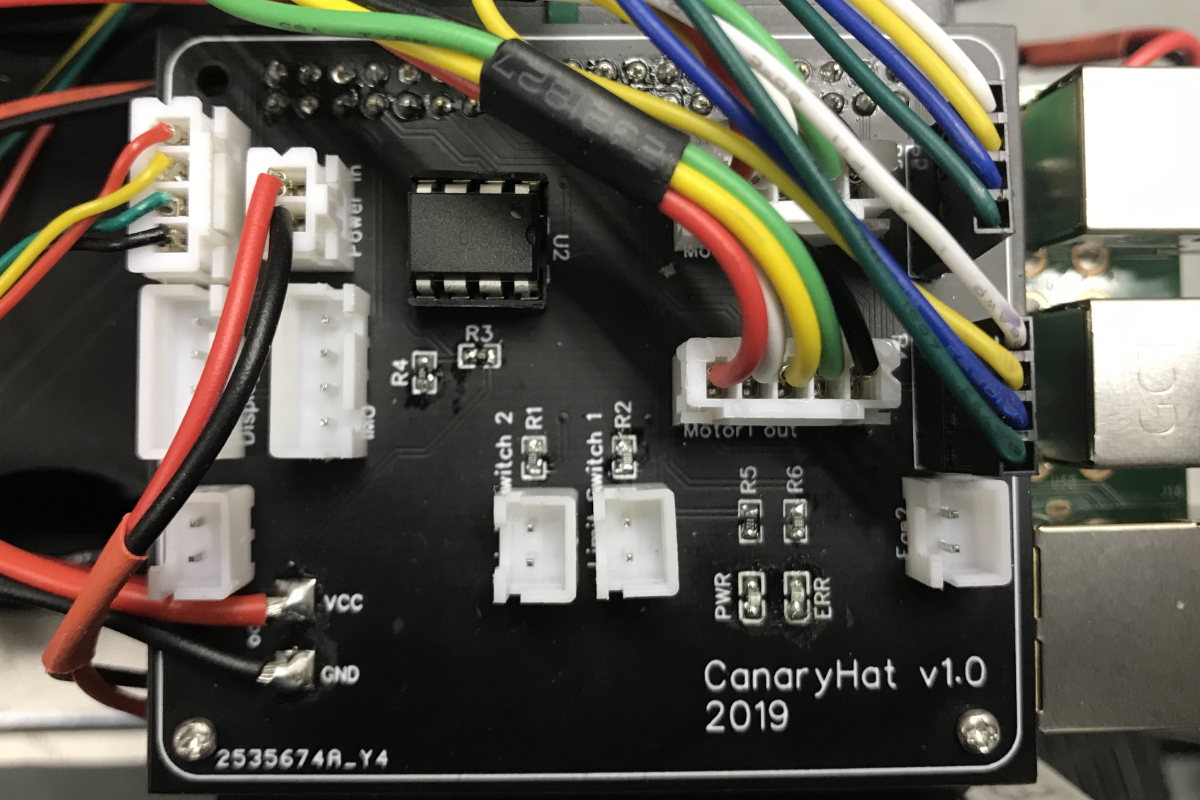
We designed a custom Pi-Hat shield for the system, ordered PCB’s and assembled the components and connectors to clean up the wiring and make the system easier to use. We added an ADC and voltage divider to monitor battery voltage and disable the motors and lidar when the batteries begin to run low.
The software is set up on the pi a system of nodes that control different functionality which all communicate using LCM. All the data collected by the lidar is handled using PCL in C++. The data collected by the robot is incrementally saved on the SD and then concatenated and exported at the end of the scan as a .pcd. This can be opened in the PCL viewer, the custom viewer we developed and can also be register with other point clouds using PCL’s registration API and post processed using the PCL filtering tools. We used a Progressive Morphological Filter base on the paper published by Zhang et al. to segment our return in to ground and non-ground returns.
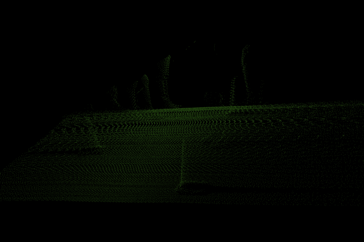
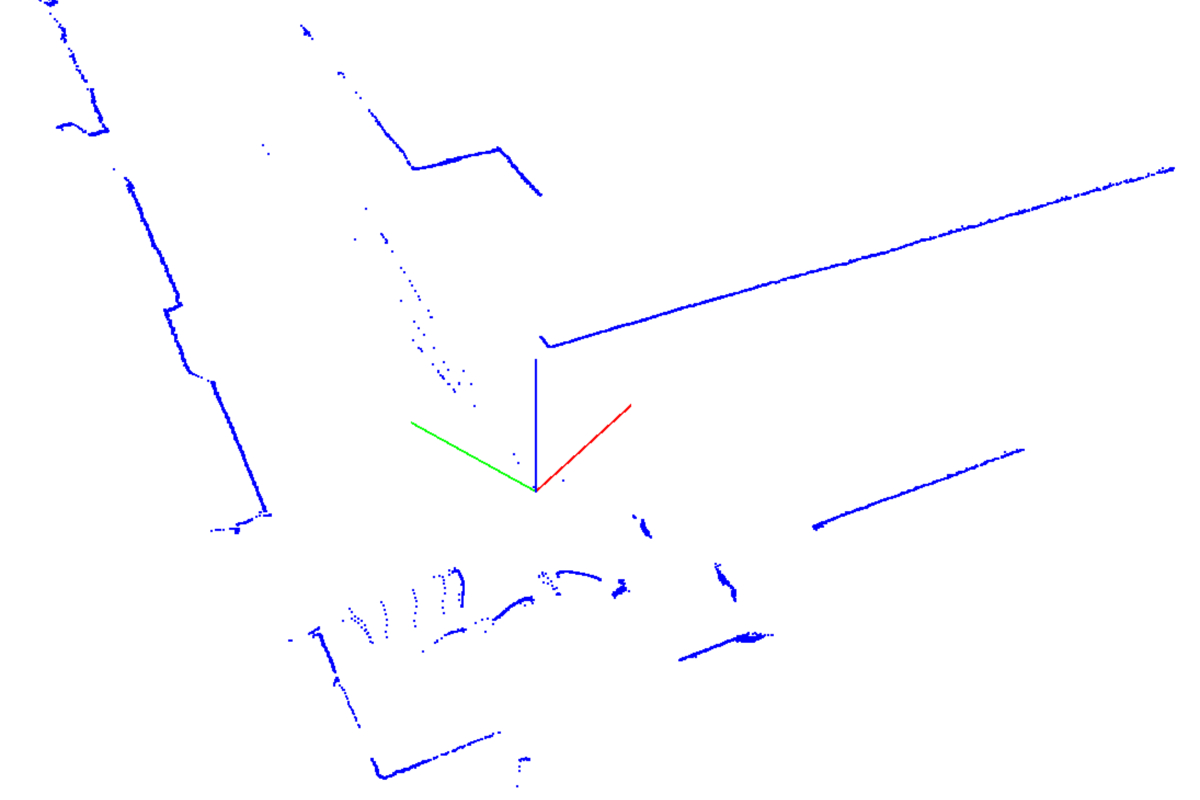
At University or Rochester design day we demoed our system on an area with a set of traffic cones, on the scan below you can see the outlines of traffic cones and even the legs and feet of a few spectators watching the demo.